Copy Write 7/8/2000© Updated 12/16/2004 Disclaimer
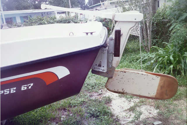
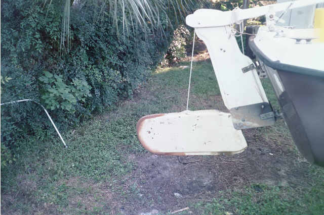
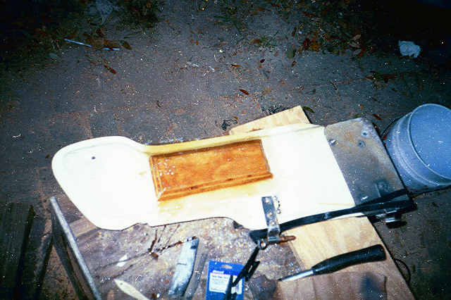
E- Mail RudderThe area where the pivot hole is has been compromised. The wood core is exposed and splitting. The rudder itself is two sheets of plywood sandwiched between fiberglass roving and gel coat. The problem is the area for the pivot pin & lock down pin. One of the plywood sides has been exposed to weather due to splitting. A grinder is used to clean out the damaged wood as deep as possible exposing most all the pivot pin hole. The lock down pin is deeper and can't be reach with the grinder. A skill saw blade will cut deeper. Carefully several passes are made and the wood cleaned. Before attempting to fill the voided area I need to do everything possible to dry the rudder. I don't have a clue how much moisture has wicked down into the rudder. Have you ever noticed how hot a closed vehicle gets during the summer? That will be my oven. Park the truck in the sun and keep the windows up as much as possible. In a week or so I will have some other projects completed and hopefully the heat will have dried out the rudder core. Some resin is poured in the slot cleaned, to level things up before the filling process. Poly resin is also used to bond 3/8ths SS washers inside the holes for the pivot pin and lock down pin. It is my delusion the washers will help take the load and reduce wear and tear. 2" fiberglass tape is thread down the slot and wet out. Quickly two additional layers are laid down. Once everything cures a grinder is used to smooth everything out. A fiberglass resin thickener is needed, Silica Micro spheres are chosen. I have never used something like this before. Sandpaper is used to smooth the slot. The first batch of resin putty is mixed. The filler doesn't mix well. It takes a bit of stirring to get white powder mixed in before adding the catalyst. The end result is like peanut butter. A screwdriver blade is used to work the resin into the low end of the slot. The low end needs to be built up first. As the resin starts to sag I quickly cut some tape to cover the outside and support the resin. The downside of this is the time involved. Small batches need to be mixed and laid in. Wait for the kick off then sand to shape. Once the low end is built up another length of tape is folded lengthwise and packed into the slot. Another batch of resin putty is mixed and laid inside the tape. Each layer filling just a bit more. Two additional lengths of tape are loaded in before the slot is narrowing enough to make it difficult get tape in and still have room to work the putty. Mixing up one big batch of putty it is time for the final application. Loading in the putty a length of tape is run along the top of the seam and wetted. I have done all I can, it is time to let the resin cure.
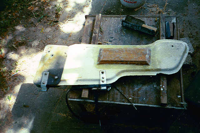
Once kicked off the grinder is used for final shaping, another layer of tape is laid along the seam edge. Another rudder concern is the lower edge. That's the edge that drags through the sand and mud. Over the years it is showing some serious wear. Resin is painted along the leading edge to make it sticky a length of 2" tape is pressed on. A layer of nonstick masking tape is run around the outside edge of the fiberglass tape. Thickened resin is poured in around the uneven edge of the rudder. The tape holds the resin and the masking tape prevents leaks. Once the resin kicks the masking tape is removed and the rudder flipped over to the other side. The same process is completed on the other side. . There is a fiberglass lip about 1" around the edge of the rudder. As mentioned above this lip has been filled in around the lower part of the rudder with resin and capped the edges with cloth. Actually it looks like a big mess. The edge of the rudder has been squared squared off the edge giving me something to work with. Running several strips of cloth along this edge, it is quickly built up. After everything kicks and hardens well, it is time to dress the edges for final shaping. Did I ever mention the grinder I bought several years ago?? Prop scaring along the port side of the rudder is also filled in. Donning eye goggles and a dust mask I make the snow fly. Fiberglass dust goes everywhere. Smoothing the fiberglass into final shape, the only thing left is a final sealer coat of resin over the entire rudder. Return GudgesThe stern is leaking just a bit. I am unsure if it is the cockpit drain or the rudder gudgeons. Gaining access is not easy. The cockpit lockers aren't big enough for me to crawl in and reach the transom. An access hatch from the cockpit liner is needed. Installing the deck plate is a simple affair. Scribe the circle drill a few pilot holes and cut. Bed & bolt the cover plate. The bolts holding the gudgeons in place are frozen, it's grinder time. From the back of the transom the face of 6 bolts is ground off. From the cockpit side the rest of the stuff is removed. Next is the drain through hull. The retaining nut is not easy to loosen (hard to reach) but eventually it gives. The thru-hull fitting is a bit different, after 20 something years the plastic is brittle. Getting the fitting to unscrew from the hull is not hard once it starts moving; it was that initial moving that was hard. End result a new thru-hull is needed. The gudgeons for the rudder are next on the list. From the looks of things I honestly believe this is the first time the mounting bolts have been replaced from original construction. Starting with the top gudgeon (big mistake) a wood backing plate is cut. The wood is too thick to use the bolts I have for the job. Rather than scrap around for another thinner piece I just grab the 1" hole drill bit and countersink one side of the backing plate. Quickly the stainless gudgeon is threaded with bolts through the transom and the backing plate. Soon the washers & nuts are tightened squeezing out the excess silicone sealer that had been gooped all over the mounting bracket. Moving down to the lower gudgeon I realize my mistake. The lower should have been done first. It is tough to reach down there. I have found by standing on the ground and reaching over the transom I am able to get one arm down in the work space. The bolts go in a triangle pattern I feed the lower center hole first, the port side and can't get the starboard side to go thru. After taking everything apart try it from starboard to port, same problem. Hmmmm my drill bit must have wandered just enough. Starting on the port side the gudgeon is mounted, bolts threaded through port and middle holes then tightened. Working like this the caulking on the bracket makes a bit of a mess. Grabbing the drill using the existing transom hole as a guide the hole in the plywood backing plate is adjusted. Apparently the hole wasn't far off because I don't drill all the way through before the bit is turning free. I have exactly three bolts left two are new and one is used. After threading the nut the last bolt is ready to tighten. I can't get it to snub up. The bolt goes in so far??? It stops a few inches short of the transom. Apparently the bolt is just long enough to bump against the vertical cockpit support brace. Lets all say this together Hmmmmm. It's late and I'm tired. Time to remove the nut and worry about it tomorrow. Initially the nut seems to work its way off, to a point then no more. I attempt to force it with the bolt giving way. Ratcheting away I soon realize I don't seem to be getting anywhere. Looks like I have problems here. Between late night working & tiredness I seemed too erred in judgment. The nut has stripped and is stuck on the bolt. Not sure why but it has. If I had thought things through the lower gudgeon should have been installed then the upper. Time to call it quits. Getting back to last night, the more I look at the situation the worse it gets. The access port I installed is great but provides little room to work. A hack saw is the only thing I can think of. It takes forever eventually I think I have a grove cut deep enough that I might be able to use vice grips to break off the rest of the bolt. This is risky because if it doesn't work and the bolt doesn't snap clean. I will end up with a bigger mess. Fortunately luck was with me the bolt breaks. A quick trip to a hardware store a replacement bolt is purchased, and installed without incident. Return Rudder AssemblyIt's time to remove the old damaged cleats off the rudder assembly. I don't want to drill any additional holes. As the cleats don't carry a big load. I think I will cut, resin and paint some plywood pads to the rudder assembly. Then go buy two cleats and screw them into the pads.
Trimming some plywood pads to fit on the rudder assembly, one pad is coated with resin and a coat is placed on the rudder assembly. Placing the pad in place fiberglass cloth is cut to bind the wood pad to the rudder assembly and wetted out. After kick off the pad is sanded to smooth the rough spots. Another layer of cloth is laid and the rudder assembly flipped to complete the other side. After the fiberglass has cured for a day or two the rudder assembly is painted. |
Return DisclaimerThe information on this page is not intended as a "definitive" guide to sailing . formated for 800 x 600 and Cascading Style Sheets Return |